Juniper Class of Service (CoS)

If you come from a Cisco Quality of Service (QoS) background then you may find converting to the way that Juniper does things a challenge at first. As an initial step, I can recommend the free Juniper e-book entitled ‘Junos QoS For IOS Engineers‘. The first thing to know is that Juniper call it Class of Service (CoS). In Cisco land, the term ‘CoS’ is used exclusively for layer 2 (802.1q) QoS, so this can be confusing initially.

As with my other Juniper posts, the configuration will be for an MX104 router. The MX series supports 16 forwarding classes and 8 output queues, which allows you to classify packets with more granularity. As there can be more forwarding classes than queues, if you configure more than 8 forwarding classes you must map multiple forwarding classes to single output queues.

We’ll be using the traffic classes that are described in RFC4594, ‘Configuration Guidelines for DiffServ Service Classes’. If you’ve seen any of the Cisco Live presentations about QoS in the last few years, then the mapping below may look familiar.

QoSMapping

First of all we need to define our 12 RFC4594 forwarding classes and then map them to the 8 output queues as per our diagram above. You will notice that some of the classes are mapped to the same queue. You may wonder why we are using more forwarding classes than there are queues available. This particular device supports 8 queues, but other devices on the network support more. We can therefore keep the application classes and DSCP markings consistent across the network but then simply map them to the supported number of queues at each hop.

set class-of-service forwarding-classes class voip-telephony queue-num 0
set class-of-service forwarding-classes class broadcast-video queue-num 0
set class-of-service forwarding-classes class real-time-interactive queue-num 0
set class-of-service forwarding-classes class network-control queue-num 1
set class-of-service forwarding-classes class signalling queue-num 1
set class-of-service forwarding-classes class ops-admin-mgmt queue-num 1
set class-of-service forwarding-classes class multimedia-conferencing queue-num 2
set class-of-service forwarding-classes class multimedia-streaming queue-num 3
set class-of-service forwarding-classes class transactional-data queue-num 4
set class-of-service forwarding-classes class bulk-data queue-num 5
set class-of-service forwarding-classes class scavenger queue-num 6
set class-of-service forwarding-classes class best-effort queue-num 7


Next we must classify traffic that has already been marked. This is a core device, so ideally we want to have marked our traffic at an earlier point in the network. As we can simply look at existing DSCP markings, we can use what’s called a Behaviour Aggregate (BA) classifier. If we wanted to classify based upon IP addresses and ports, we could use a multifield classifier along with a firewall filter.

set class-of-service classifiers dscp ba-classifier-rfc4594 forwarding-class voip-telephony loss-priority high code-points ef
set class-of-service classifiers dscp ba-classifier-rfc4594 forwarding-class broadcast-video loss-priority high code-points cs3
set class-of-service classifiers dscp ba-classifier-rfc4594 forwarding-class real-time-interactive loss-priority high code-points cs4
set class-of-service classifiers dscp ba-classifier-rfc4594 forwarding-class multimedia-conferencing loss-priority high code-points [ af41 af42 af43 ]
set class-of-service classifiers dscp ba-classifier-rfc4594 forwarding-class multimedia-streaming loss-priority high code-points [ af31 af32 af33 ]
set class-of-service classifiers dscp ba-classifier-rfc4594 forwarding-class network-control loss-priority high code-points [ cs6 cs7 ]
set class-of-service classifiers dscp ba-classifier-rfc4594 forwarding-class signalling loss-priority high code-points cs5
set class-of-service classifiers dscp ba-classifier-rfc4594 forwarding-class ops-admin-mgmt loss-priority high code-points cs2
set class-of-service classifiers dscp ba-classifier-rfc4594 forwarding-class transactional-data loss-priority high code-points [ af21 af22 af23 ]
set class-of-service classifiers dscp ba-classifier-rfc4594 forwarding-class bulk-data loss-priority high code-points [ af11 af12 af13 ]
set class-of-service classifiers dscp ba-classifier-rfc4594 forwarding-class scavenger loss-priority high code-points cs1
set class-of-service classifiers dscp ba-classifier-rfc4594 forwarding-class best-effort loss-priority high code-points be

In the above configuration we are creating a BA classifier named ‘ba-classifier-rfc4594’ and then assigning our DSCP markings (EF, CS1, AF11 etc) to each of the forwarding classes that we defined earlier.

Loss priorities allow us to specify different drop profiles for certain types of traffic. Drop profiles tell the router how to drop packets when an interface is congested. For simplicity we keep the loss priority set to high for all forwarding classes. We will reference this ‘high’ value later and assign a drop profile.

Once the classifier is complete, we must apply it to each interface that will receive traffic that has already been marked. If you are using sub interfaces, the classifier should be applied to each sub-interface and not to the physical interface.

set class-of-service interfaces ge-0/1/0 unit 210 classifiers dscp ba-classifier-rfc4594
set class-of-service interfaces ge-0/1/0 unit 211 classifiers dscp ba-classifier-rfc4594
set class-of-service interfaces ge-0/1/1 unit 210 classifiers dscp ba-classifier-rfc4594
set class-of-service interfaces ge-0/1/1 unit 211 classifiers dscp ba-classifier-rfc4594

So far we have our forwarding classes which have been mapped to queues. We have a BA classifier that will inspect the DSCP markings on incoming packets and put them in the correct forwarding class. We now need to allocate available bandwidth across those queues using a scheduler.

You can think of a scheduler as a cashier that is servicing multiple queues of customers at once. The cashier will pick two people from queue one, five people from queue two etc. As you can imagine, queue two would reduce in length at a much faster rate than queue one. The number of customers picked from each queue at a time by the cashier would be the bandwidth allocation and the queue that they choose to serve first would be determined by the priority.

set class-of-service schedulers real-time transmit-rate percent 20
set class-of-service schedulers real-time priority high

set class-of-service schedulers control transmit-rate percent 10
set class-of-service schedulers control priority medium-high

set class-of-service schedulers multimedia-conferencing transmit-rate percent 10
set class-of-service schedulers multimedia-conferencing priority medium-high
set class-of-service schedulers multimedia-conferencing drop-profile-map loss-priority high protocol any drop-profile high-drop

set class-of-service schedulers multimedia-streaming transmit-rate percent 10
set class-of-service schedulers multimedia-streaming priority medium-high
set class-of-service schedulers multimedia-streaming drop-profile-map loss-priority high protocol any drop-profile high-drop

set class-of-service schedulers transactional-data transmit-rate percent 10
set class-of-service schedulers transactional-data priority medium-high
set class-of-service schedulers transactional-data drop-profile-map loss-priority high protocol any drop-profile high-drop

set class-of-service schedulers bulk-data transmit-rate percent 8
set class-of-service schedulers bulk-data priority low
set class-of-service schedulers bulk-data drop-profile-map loss-priority high protocol any drop-profile high-drop

set class-of-service schedulers scavenger transmit-rate percent 2
set class-of-service schedulers scavenger priority low

set class-of-service schedulers best-effort transmit-rate percent 30
set class-of-service schedulers best-effort priority medium-low
set class-of-service schedulers best-effort drop-profile-map loss-priority high protocol any drop-profile high-drop

There are a few things to point out in the above configuration. We start by creating 8 schedulers, one for each of the 8 queues supported on the MX series router. These are named according to the queues in the mapping diagram above. Each scheduler is given a certain percentage of the interface bandwidth and a priority.

Priorities determine the order in which queues have access to the outgoing interface. The available priorities are low, medium-low, medium-high, high and strict-high. Strict-high is similar to the priority queue in Cisco land, although as you can only map a single forwarding class to it, we’ve used high here instead.

Some of the schedulers reference a drop profile named ‘high-drop’ that is utilised when a loss-priority of ‘high’ has been set by our BA classifier. We will create this drop profile later on. The drop profiles are associated with queues that contain primarily TCP traffic and that would benefit from Weighted Random Early Detect (WRED).

The individual schedulers now need to be mapped to forwarding-classes with a scheduler map. As we have multiple forwarding-classes tied to certain queues, the forwarding-classes that share a queue must all reference the same scheduler.

set class-of-service scheduler-map scheduler-8q forwarding-class voip-telephony scheduler real-time
set class-of-service scheduler-map scheduler-8q forwarding-class broadcast-video scheduler real-time
set class-of-service scheduler-map scheduler-8q forwarding-class real-time-interactive scheduler real-time
set class-of-service scheduler-map scheduler-8q forwarding-class network-control scheduler control
set class-of-service scheduler-map scheduler-8q forwarding-class signalling scheduler control
set class-of-service scheduler-map scheduler-8q forwarding-class ops-admin-mgmt scheduler control
set class-of-service scheduler-map scheduler-8q forwarding-class multimedia-streaming scheduler multimedia-streaming
set class-of-service scheduler-map scheduler-8q forwarding-class multimedia-conferencing scheduler multimedia-conferencing
set class-of-service scheduler-map scheduler-8q forwarding-class transactional-data scheduler transactional-data
set class-of-service scheduler-map scheduler-8q forwarding-class bulk-data scheduler bulk-data
set class-of-service scheduler-map scheduler-8q forwarding-class scavenger scheduler scavenger
set class-of-service scheduler-map scheduler-8q forwarding-class best-effort scheduler best-effort

Next, the above scheduler map named ‘scheduler-8q’ needs to be assigned to each interface. This should be the physical interface even if you have sub-interfaces configured.

set class-of-service interfaces ge0/1/0 scheduler-map scheduler-8q
set class-of-service interfaces ge0/1/1 scheduler-map scheduler-8q

On transit interfaces where we might not trust the DSCP markings that are set on the incoming packets, we need to enforce the best-effort forwarding class. This prevents untrusted traffic from marking everything as voice (our highest priority queue) and starving our other traffic of bandwidth. To do this we can use a fixed classifier that specifies a single forwarding class that all traffic will be placed into.

set class-of-service interfaces ge0/0/0 unit 0 forwarding-class best-effort

All sorted, right? Well, not really. Although our traffic will leave this router in the correct queue, we haven’t changed the DSCP marking. The next router might use a BA classifier and will classify the traffic based upon the untrusted DSCP marking. To resolve this, we need to define rewrite rules. The important point to note here is that a packet’s DSCP marking is only changed as it leaves the router on the egress interface.

High Loss Priority:
set class-of-service rewrite-rules dscp rewrite-rfc4594 forwarding-class voip-telephony loss-priority high code-point ef
set class-of-service rewrite-rules dscp rewrite-rfc4594 forwarding-class broadcast-video loss-priority high code-point cs3
set class-of-service rewrite-rules dscp rewrite-rfc4594 forwarding-class real-time-interactive loss-priority high code-point cs4
set class-of-service rewrite-rules dscp rewrite-rfc4594 forwarding-class multimedia-conferencing loss-priority high code-point af41
set class-of-service rewrite-rules dscp rewrite-rfc4594 forwarding-class multimedia-streaming loss-priority high code-point af31
set class-of-service rewrite-rules dscp rewrite-rfc4594 forwarding-class network-control loss-priority high code-point cs6
set class-of-service rewrite-rules dscp rewrite-rfc4594 forwarding-class network-control loss-priority high code-point cs7
set class-of-service rewrite-rules dscp rewrite-rfc4594 forwarding-class signalling loss-priority high code-point cs5
set class-of-service rewrite-rules dscp rewrite-rfc4594 forwarding-class ops-admin-mgmt loss-priority high code-point cs2
set class-of-service rewrite-rules dscp rewrite-rfc4594 forwarding-class transactional-data loss-priority high code-point af21
set class-of-service rewrite-rules dscp rewrite-rfc4594 forwarding-class bulk-data loss-priority high code-point af11
set class-of-service rewrite-rules dscp rewrite-rfc4594 forwarding-class scavenger loss-priority high code-point cs1
set class-of-service rewrite-rules dscp rewrite-rfc4594 forwarding-class best-effort loss-priority high code-point be

Low Loss Priority:
set class-of-service rewrite-rules dscp rewrite-rfc4594 forwarding-class voip-telephony loss-priority low code-point ef
set class-of-service rewrite-rules dscp rewrite-rfc4594 forwarding-class broadcast-video loss-priority low code-point cs3
set class-of-service rewrite-rules dscp rewrite-rfc4594 forwarding-class real-time-interactive loss-priority low code-point cs4
set class-of-service rewrite-rules dscp rewrite-rfc4594 forwarding-class multimedia-conferencing loss-priority low code-point af41
set class-of-service rewrite-rules dscp rewrite-rfc4594 forwarding-class multimedia-streaming loss-priority low code-point af31
set class-of-service rewrite-rules dscp rewrite-rfc4594 forwarding-class network-control loss-priority low code-point cs6
set class-of-service rewrite-rules dscp rewrite-rfc4594 forwarding-class network-control loss-priority low code-point cs7
set class-of-service rewrite-rules dscp rewrite-rfc4594 forwarding-class signalling loss-priority low code-point cs5
set class-of-service rewrite-rules dscp rewrite-rfc4594 forwarding-class ops-admin-mgmt loss-priority low code-point cs2
set class-of-service rewrite-rules dscp rewrite-rfc4594 forwarding-class transactional-data loss-priority low code-point af21
set class-of-service rewrite-rules dscp rewrite-rfc4594 forwarding-class bulk-data loss-priority low code-point af11
set class-of-service rewrite-rules dscp rewrite-rfc4594 forwarding-class scavenger loss-priority low code-point cs1
set class-of-service rewrite-rules dscp rewrite-rfc4594 forwarding-class best-effort loss-priority low code-point be

Above we have configured a rewrite rule named ‘rewrite-rfc4594’ and have specified DSCP markings for each forwarding class. There are two sets of rules to cover different loss priorities, but they are still the same markings. If we take our fixed classifier example from above, the packet with an untrusted marking will come in, be forced into the best effort forwarding class and will then be remarked to best effort (CS0) as it leaves the router on a different interface.

We need to apply the above rewrite rules to our interfaces and sub-interfaces.

set class-of-service interfaces ge-0/0/0 unit 0 rewrite-rules dscp rewrite-rfc4594
set class-of-service interfaces ge-0/1/0 unit 210 rewrite-rules dscp rewrite-rfc4594
set class-of-service interfaces ge-0/1/0 unit 211 rewrite-rules dscp rewrite-rfc4594
set class-of-service interfaces ge-0/1/1 unit 210 rewrite-rules dscp rewrite-rfc4594
set class-of-service interfaces ge-0/1/1 unit 211 rewrite-rules dscp rewrite-rfc4594

Bear with me, we are nearly done. If our circuit provider limits our bandwidth, we should shape our outbound traffic so that it is dropped sooner rather than later. Here we shape our outbound traffic to 500Mbps.

set class-of-service interfaces ge0/1/0 shaping-rate 500m
set class-of-service interfaces ge0/1/1 shaping-rate 500m

If you remember, we still need to define the drop profile named ‘high-drop’ that we referenced in the schedulers earlier. The following configuration tells the router to start dropping packets when the buffer is 50% full with a probability of 1% and then increase the drop probability gradually (interpolating the values) until the buffer is 100% full. This means that when the buffer is 60% full there is a 25% chance of the packet being dropped and so on. Once defined, you can use the command ‘show class-of-service drop-profile high-drop’ to show the full table of fill levels versus drop probabilities.

set class-of-service drop-profiles high-drop interpolate fill-level [50 70 90]
set class-of-service drop-profiles high-drop interpolate drop-probability [1 50 90]

By default, traffic sourced from the router such as OSPF, SNMP etc uses queues 0 and 3. In our design we have network control traffic in queue 1, so this doesn’t work for us. To change all router traffic to a different forwarding class, you can use the following command.

set class-of-service host-outbound-traffic forwarding-class network-control

We can verify our configuration with the command ‘show interfaces ge-0/0/0 extensive’. This will show us the number of packets seen in each queue, the forwarding class to queue mapping and the bandwidth allocation for each queue.

Phew, we’re done. The full configuration can be seen here. The diagram below should help you to visualise the mapping between the different configuration parts.

One aspect that isn’t really intuitive if you come from a Cisco background is the mapping between forwarding classes and the scheduler maps. It feels like they should be mapped to the queues, but they are mapped to the forwarding classes that are in turn mapped to the queues. As you can have more forwarding classes than queues, this means that you have to ensure that your forwarding class to scheduler mappings match your forwarding class to queue mappings.

JuniperCoS

Well, that’s all I have to say about that. Have fun!

Juniper MIC With Third-Party Optics Issue

We have been experiencing an intermittent issue over the last couple of months with our Juniper MX104 routers. After a few weeks of continuous operation, the Modular Interface Card (MIC) will suddenly stop passing traffic. As our 4G console servers are still on order, this has resulted in a few day trips to our data centres.

JuniperMX104

When the issue has occurred, the routers will still be up and running but the MIC is non-responsive. We send logs to a syslog server, but because connectivity was down this obviously wasn’t working. This meant that we had to get to the device before the logs were overwritten and also copy any core dump files for the open Juniper Technical Assistance Centre (JTAC) case.

We tracked down the following entries in the logs, which eventually pointed us at this Juniper Knowledge-base article.


afeb0 MIC0 IX PCI Fatal Error detected.
afeb0 Ixchip(0): pio_handle(0x4c915b70); pio_read_u32() failed: 20(input/output error)! ge-addr=01105e04
afeb0 ixchip_env_check: Too many IXCHIP 0 IO errors, stop subsequent IXCHIP READ/WRITE operations 

We came to the conclusion that our third-party optics were to blame. Unfortunately we had a few failures of genuine Juniper optics and were forced to use third party optics. We’ve generally had no issue with using third-party optics on other devices, but unfortunately that run of good luck has come to an end.

One of the possible symptoms of this issue is that the i2c failure count will increase for the third party SFPs. This can be seen with the following commands.


start shell pfe network afeb0
show sfp list 

This will show a list of the SFPs that are installed and their serial numbers. You can see from the output below that there are three with one type of serial number and three with another.


Index Name Presence ID Eprom PNO SNO calibr Toxic
----- -------------- ---------- -------- ---------- ----------- ------- -------
 1 MIC(0/0)(0) Present Complete 740-031850 AC1345SA3XF int Unknown
 2 MIC(0/0)(1) Present Complete 740-031850 AC1567SA3BD int Unknown
 3 MIC(0/0)(2) Present Complete 740-031850 AC1987SA3BX int Unknown
 4 MIC(0/0)(3) Present Complete 740-011783 F143JU01323 int Unknown
 5 MIC(0/0)(4) Present Complete 740-011783 F143JU01345 int Unknown
 6 MIC(0/0)(5) Present Complete 740-011783 F143JU01312 int Unknown

Looking through the info for each of the SFP index numbers shows that one has a non-zero error count.

MX104-ABB-0(HSTNM vty)# show sfp 5 info
index: 0x05
sfp name: MIC(0/0)
pic context: 0x4DC15170
id mem scanned: true
linkstate: Up
sfp_present: true
sfp_changed: false
i2c failure count: 0x2B (NON ZERO)
diag polling count: 0x504
no diag polling from RE:0x1
run_periodic: false

After removing the three third-party SFPs, the MIC has been stable for a number of weeks, let’s hope that it stays that way. Thankfully we’ve not gone live on the routers yet.

Network Automation – Part 2

As mentioned in Part 1, the Network Interrogation Tool (NIT) is a web service written in Python/Flask that sits in the middle between SolarWinds and Rundeck to provide Rundeck with the various lists of options that the user must select for each job.

I’ll start with a very basic overview of Flask, but any web framework could be used for this layer. The primary goal is to get useful data out of your various tools and format them ready for Rundeck.

Flask is just one of many web frameworks that can be utilised in the Python programming language to build a web-based application. It is a micro framework, as opposed to something like Django which is a full-blown solution that contains all kinds of features already built-in. I would have probably used Django if I hadn’t discovered Rundeck, but as NIT was to be a relatively straightforward project, I decided to keep it simple with Flask.

The Flask quick start guide is a good resource if you want details, but for now it is enough to know that you can use the ‘route’ decorator to tell Flask what URLs should trigger your functions. If you are familiar with MVC, these would be analogous to controllers.


from flask import Flask
app = Flask(__name__)

@app.route('/subnets/list/', defaults={'output': 'html'})
@app.route('/subnets/list/')
def subnets_list(output):
# Subnet list code here.

Once the above application is loaded, a user navigating to ‘yourdomain.com/subnets/list’ would trigger the code contained within the subnets_list function. You can also see that we have defined an optional string variable named ‘output’. If nothing is appended to the URL, the string will default to ‘html’. You can capture a number of variables in this way, but in this case we are using it to switch between different outputs such as HTML or JSON.

When /json is appended to the URL, we then use Flask’s ‘jsonify()’ method to format Python lists as JSON and then return them to the browser. If the user doesn’t append anything then it will default to a HTML view. The HTML view is generated using Flask’s ‘render_template()’ method.

def subnets_list(output):
    # Object creation and error handling omitted.

    if output.lower() == 'json':
        # Convert list of Subnet objects into a list of tuples.
        json_subnets = []

        for subnet in subnets.list:
            json_subnets.append((str(subnet.netaddress), subnet.name))

        return jsonify(json_subnets)
    else:
        # Populate the title and description for the view.
        title = 'Subnets'
        description = 'This is a live list of subnets fed from NMS. ' \
                      'Append \'/json\' to the url for the Json endpoint.'

        # Populate the table's headers.
        table_headers = ['Subnet', 'Name']

        # Populate a list of tuples with data.
        table_data = []

        for subnet in subnets.list:
            table_data.append((subnet.netaddress, subnet.name))

        return render_template('table.html',
                               title=title,
                               description=description,
                               table_headers=table_headers,
                               table_data=table_data)

The ‘render_template()’ method takes a template file as a parameter. This template file needs to be written in HTML along with the templating engine Jinja2. The example code snippet below shows a table header being generated from a passed list named ‘table_headers’. By passing our page title, description, table headers and table data into the template, we can dynamically generate pages while using a single template file.


<thead>
    <tr>
        {% for header in table_headers %}
            <th>{{ header }}</th>
        {% endfor %}
    </tr>
</thead>

The HTML/CSS itself utilises the popular CSS library Bootstrap. With Bootstrap you can easily create responsive pages with navigation bars, image carousels etc.

While developing your application locally, Flask will start a basic web server on your PC for testing. This test server shouldn’t be used in production and you will need to integrate your application with a proper web server, such as Apache. To integrate Apache with your Flask application, a Web Server Gateway Interface (WSGI) file is used. The WSGI file (shown below), tells Apache how to start your application.

import sys
sys.path.insert(0, '/opt/scripts/nit')

from nit import app as application

You can then reference the .wsgi file from your httpd.conf file. You will also need to install mod_wsgi and restart Apache.


   ServerName nit.yourdomain.com
   WSGIScriptAlias / /opt/scripts/nit/apache/nit.wsgi
   WSGIDaemonProcess nit.yourdomain.com user=scripts group=scripts processes=2 threads=25
   WSGIProcessGroup nit.yourdomain.com

   
      Require all granted
   

Now that we have covered the web front-end of NIT, that front-end needs some data to display. This data is fetched from SolarWinds and manipulated by a set of wrapper classes and their methods. Below is the code that we might use within our previously shown ‘subnets_list’ function to instantiate an object from our ‘Subnets’ class.


# Instantiate a SolarWinds API instance using the
# details from the application config file.
sw_api = solarwinds.Api(app.config['SW_APIURL'], app.config['SW_USERNAME'], app.config['SW_PASSWORD'])

# Pass the above API to the constructor of Subnets.
subnets = nms.Subnets(sw_api)

The ‘Subnets’ class (shown below) takes an instance of the SolarWinds API in its constructor. This API is then used within a list property to fetch all subnets from our IP Address Management (IPAM) system using SQL-like statements that the SolarWinds API expects.

It then iterates through the results, instantiates a new Subnet (singular) object for each record and then adds those new objects to a Python list. Finally it returns the list of ‘Subnet’ objects to the calling function.


class Subnets(object):
    '''Subnets class.
    Attributes:
        sw_api: A SolarWinds API instance.
    '''
    def __init__(self, sw_api=None):
        if sw_api is None:
            raise errors.Error('[%s.%s] - You must provide a SolarWinds API instance.' % (__name__, self.__class__.__name__))
        else:
            self.sw_api = sw_api

    @property
    def list(self):
        '''Get a list of subnets and their details from SolarWinds.
        Returns:
            A list of subnet objects.
        '''
        sw_subnets = self.sw_api.query('SELECT DISTINCT Address, CIDR, FriendlyName FROM IPAM.Subnet ';
                                       'WHERE Address IS NOT NULL AND AddressMask IS NOT NULL')

        subnets_list = []

        for sw_subnet in sw_subnets['results']:
            if '0.0.0.0' not in str(sw_subnet['Address']):
                new_subnet = Subnet(str(sw_subnet['Address']) + '/' + str(sw_subnet['CIDR']), sw_subnet['FriendlyName'])
                subnets_list.append(new_subnet)

        return subnets_list

class Subnet(object):
    '''Subnet class.
    Attributes:
        netaddress: The network address in IP/CIDR format.
        name: The subnet's name, if available.
    '''
    def __init__(self, netaddress=None, name=''):

        if netaddress is None:
            raise errors.Error('[%s.%s] - You must provide a network address for the subnet in CIDR format.';
                               % (__name__, self.__class__.__name__))
        else:
            self.netaddress = IPNetwork(netaddress)
            self.name = name

The ‘list’ property of the class is subsequently used within our decorated Flask functions to output the subnets as JSON that Rundeck can utilise.

NITAvailJson

Another property of the Subnets class is ‘available’, which utilises the netaddr library to return a list of the largest available subnets that can still be utilised. This is the HTML template view without the ‘/json’ appended to the URL.

NITAvailable

Similarly, the class method ‘available_bysize()’ takes a CIDR value (24, 25 etc) and returns a list of available subnets that match the given size.

Your requirements and data repositories may be different, but hopefully this has served as an overview of how you might get data out of your own tools and formatted as JSON endpoints. Once all of your required endpoints are available and are displaying the correct data, you can now use those URLs in Rundeck to provide choices to your users when they are preparing automation jobs.

RundeckRemoteURLJson

The user is now forced to select a valid subnet that we can be confident is available.

RundeckAvailableSubnets

In Part 3 we will discuss what happens when a user executes a job from within Rundeck.

Peering

Historically as an organisation we had simply connected to the Internet via resilient managed connections from a single provider. This had worked well for the most part, but was a little restrictive when we had experienced transient issues between our data centre and remote sites or Software-as-aService (SaaS) companies like Microsoft Office 365. A problem at the peering point between our service provider and Microsoft would result in an outage on a path that we couldn’t move away from. All we could do was report it and wait.

In addition, as our IP addressing was from the service provider’s own block, we would need to change all of the IPs on our Internet-facing services just to move to a different provider if we were not receiving a good service.

The answer to these weaknesses was to obtain our own publicly routable IP address block and form peering relationships with providers ourselves using the Border Gateway Protocol (BGP). BGP is the routing protocol of the Internet. To connect your browser to this website, some of the routers along the path will be running BGP.

The first step was to register with our Regional Internet Registry (RIR). As we are based in the UK we are covered by RIPE NCC. Depending upon where you are in the world, your registry may be different.

  • African Network Information Center (AFRINIC) – Africa
  • American Registry for Internet Numbers (ARIN) – United States, Canada, Caribbean Region & Antarctica
  • Asia-Pacific Network Information Centre (APNIC) – Asia, Australia, New Zealand
  • Latin America and Caribbean Network Information Centre (LACNIC) – Latin America
  • Réseaux IP Européens Network Coordination Centre (RIPE NCC) – Europe, Russia, Middle East & Central Asia

Regional_Internet_Registries_world_map.svg

Registration means that your organisation becomes a Local Internet Registry (LIR). At the time of writing, the fees are 2000 EUR one-time registration fee and an annual subscription of 1400 EUR.

As part of the subscription, RIPE NCC run a number of courses in most countries within the region. I can personally recommend the LIR & RIPE Database course as a good overview of your new membership. As an LIR, it will be your responsibility to update the RIPE database with your IP assignments.

As IPv4 address space is extremely limited, each new LIR will receive a single /22 block of IP addresses (1024 addresses). There are fewer limitations on IPv6 address space and any LIR can request a /32 block (79,228,162,514,264,337,593,543,950,336 addresses) if they have plans to use it within two years.

In addition to your shiny new IP block, you need to request another resource from your RIR. To be able to peer with BGP you will need an Autonomous System (AS) number. The AS number represents your organisation and can have multiple IP subnets announced from it. They come in 16bit and 32bit variants, although the shorter 16bit numbers are limited and you may need a good reason if requesting them. This reason is usually that you are peering with older equipment which doesn’t support 32bit AS numbers.

Aside from a few other metrics such as weight and local preference, the BGP path selection algorithm will choose the path that traverses the fewest number of Autonomous Systems. BGP doesn’t care if there are 2 routers or 200 within an AS, although the algorithm could be influenced with a number of methods if the 200 router path was taken.

Now that we have our number resources, what do we do with them? You will need a decent router that is capable of running BGP and accepting the full Internet routing table if required. You can choose to just accept a default route (or a partial set of routes) from your provider(s), although if you want some flexibility with the route that your traffic takes then you will want full tables and multiple providers. Your choice of router will need to be based upon your own traffic levels and feature requirements, but I can definitely recommend either the Juniper MX series or Cisco ASR1k series as good starting points. I won’t go into the detail of configuring BGP here, although my previous post on Juniper BGP Peering might be a good place to look for some examples.

JuniperMX104

Juniper MX104

Where do we put these new routers? You could simply order circuits back to your premises from a transit provider and peer with BGP. This would work, but then if you want to change provider or add different peering relationships you will need to install new circuits or at least work with your provider to get that traffic to you over the existing circuit. Anyone who has ordered fibre circuits in the UK knows that it takes months and consistently makes you want to stick things in your eyes, so the fewer we need to order the better.

What if there were a location where hundreds of different providers and organisations were located and you could simply connect between routers hosted in the same building? You could then install your router in this location and connect to it there from your own premises. Well, this is what an Internet Exchange Point (IXP) is. IXPs such as the London Internet Exchange (LINX) or London Network Access Point (LONAP) are basically networks of Ethernet switches (known as peering LANs) to which members can connect their routers for easy peering between themselves. IXPs are usually situated in large data centres, such as the various Equinix and Telehouse facilities in London.

HEX

Harbour Exchange, London Docklands (Equinix LD8)

If you join an IXP such as LINX or LONAP, this is known as public peering. You are connecting to other members over a shared LAN for mutual benefit. As you are connecting directly, you will no longer pay transit fees when sending traffic between you and the path will be direct instead of via other networks. The benefits of joining an IXP will need to be weighed with the membership costs (currently £1200 per year for LINX as an example).

You can also negotiate private peering with other organisations. To connect privately, you arrange for a cross-connect between racks in your data centre facility. Cross-connects are usually purchased from the data centre operator and have a setup charge and an annual rental. The charges differ significantly per data centre, but as a very rough guide expect to pay £1000 for setup and another £1000 per year.

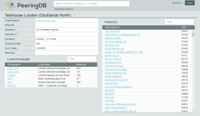
As most of the IXP data centres are popular, they are usually a good choice for private peering as well as public. To find a suitable facility you can use the peering database. PeeringDB lists most facilities and the organisations with a Point-of-Presence (POP) there. The database also lists the peering policies for those organisations so that you can check their requirements.

PeeringDB

So, you have done your research and have chosen facilities with access to IXPs and good private peering options. You will now need rack space and power for your router. The first thing to know is that this is expensive real estate. Unless you are a large organisation who needs a number of racks or you have a plan to host servers, you will probably want to rent a quarter or half a rack from a reseller. Have a look at your chosen facilities website to find a list of their resellers.

Security is understandably high at most facilities, so don’t expect to be able to turn up unannounced. You will usually need an access request code from your reseller in advance of your visit for the specific floor and suite. Ensure that you take photo identification and allow for additional time to go through procedures such as training your biometric scans.

We have briefly discussed public and private peering, which would provide better paths to specific networks, but how do we access the rest of the Internet? This is where transit comes in. You are usually not allowed to use an IXPs peering LAN for transit, so you will need another private peering and cross-connect. The difference here is that the provider would send you not just their own routes but either a default route or the full Internet routing table.

IP transit companies vary significantly in both cost and quality. To save on circuit costs, you might want to choose a company which already have a point-of-presence in your data centre. The transit companies with the best connectivity are usually the large ‘Tier 1’ providers, although there a plenty of other providers who are large but are not currently classified as Tier 1 (Cogent, Hurricane Electric etc).

Tier 1 means that the provider can reach every other network on the Internet without paying for transit or peering. Often, your local ISP is a Tier 2 or Tier 3 provider, meaning that they purchase transit to reach a portion of the Internet. If you’ve not been involved in peering then you can be forgiven for not knowing some of the big Tier 1 players listed below.

  • Level 3 Communications
  • Global Telecom & Technology (GTT)
  • NTT Communications
  • Telia Carrier
  • Tata Communications
  • Liberty Global

Transit not only provides you with access to the rest of the Internet, but they will also announce your own prefixes so that everyone else can reach you. It may be that your public and private peerings also receive your routes again, but as they can get to you directly, that path will be the favoured unless it goes down.

BGPView

ThousandEyes BGP Monitor View – Worldwide Prefix Reachability

You will probably need out-of-band access to your remote router, as you don’t want to have to drive for hours just to reverse a bad keystroke. With Juniper you have the wonderful ‘commit confirmed’ command that will rollback your changes automatically after 10 minutes unless you type ‘commit’ again, but it still helps to have console access occasionally. We have just ordered a couple of the OpenGear 4G Console Servers, so I’ll no doubt do a post about those once we deploy them.

In the words of Forrest Gump, that’s all I have to say about that.

Juniper BGP Configuration

This week marked another milestone in our Internet upgrade project, with the completion of a second transit peering to a tier 1 provider. I’m working on a separate post about peering in general, but for now let’s look how it’s done from a Juniper BGP perspective.

Creating a BGP session on a Juniper MX series is a relatively straightforward process, but you need to be careful with routing policies if you don’t want to become transit for your other peers.

transitforpeers

Let’s start by defining a couple of policies. We are receiving full Internet routing tables from our transit provider, so this import policy simply filters out smaller prefixes such as /27-/32. Most transit providers filter out anything smaller than a /24, but this policy just reduces the size of the table if that hasn’t been done upstream. At the time of writing, the full Internet routing table is at 678,760 routes (source). As the number of routes has an impact on router performance, it’s important to keep the table as small as possible.

If your provider is not already doing it upstream, you should also filter for bogons, like the IP ranges used in this post that are reserved for documentation (RFC5737).

[edit policy-options]
policy-statement no-small-prefixes {
	from {
		route-filter 0.0.0.0/0 prefix-length-range /27-/32 reject
	}
}

Set Commands:
set policy-options policy-statement no-small-prefixes from route-filter 0.0.0.0/0 prefix-length-range /27-/32 reject

Next we need a route to announce. It’s a good practice to define either an aggregate route or a static summary discard route (a.k.a null route) when announcing our prefix to the Internet, so that things stay relatively stable.

If we are using only part of the range, those routes will be more specific so will take precedence over the summary route. Anything that comes to us for parts of the range that haven’t been used will simply be discarded.

[edit routing-options static]
route 203.0.113.0/24 discard;

Set Commands:
set routing-options static route 203.0.113.0/24 discard

Now we need a policy to announce the above static route but nothing else. Be very careful here, as the default routing policy action for BGP is as follows.

Readvertise all active BGP routes to all BGP speakers, while following protocol-specific rules that prohibit one IBGP speaker from readvertising routes learned from another IBGP speaker, unless it is functioning as a route reflector.

This means that if we don’t put an explicit reject term below our accept term, the default action will be to advertise all active routes in our table, including any from a second transit peer. This could make our network the better path to some of our other peers, and this is almost certainly not what you want. Thankfully most transit providers will filter on their side as well, but it’s best to make sure with our own policies.

[edit policy-options]
policy-statement announce {
    term 1 {
        from {
            protocol static;
            route-filter 203.0.113.0/24 exact;
        }
        then accept;
    }
    term 2 {
        then reject;
    }
}

Set Commands:
set policy-options policy-statement announce term 1 from protocol static
set policy-options policy-statement announce term 1 from route-filter 203.0.113.0/24 exact
set policy-options policy-statement announce term 1 then accept
set policy-options policy-statement announce term 2 then reject

Now that we have all of our policies in place, it’s time to configure BGP. The configuration below is for a single session with imaginary transit AS65100 from our own imaginary AS65000 (AS numbers 64512 to 65535 are reserved for private use or documentation).

In reality you will probably want multiple external peers for resilience and an internal BGP (iBGP) configuration to distribute those routes around your own network.

[edit routing-options]
autonomous-system 65000

[edit protocols bgp]
group ebgp-65100 {
 type external;
 description "*** eBGP with Transit (AS65100) ***";
 import no-small-prefixes;
 authentication-key "passwordhere";
 export announce;
 peer-as 65100;
 neighbor 198.51.100.1;
}

Set Commands:
set routing-options autonomous-system 65000
set protocols bgp group ebgp-65100 type external
set protocols bgp group ebgp-65100 description "*** eBGP with Transit (AS65100) ***"
set protocols bgp group ebgp-65100 import no-small-prefixes
set protocols bgp group ebgp-65100 authentication-key "passwordhere"
set protocols bgp group ebgp-65100 export announce
set protocols bgp group ebgp-65100 peer-as 65100
set protocols bgp group ebgp-65100 neighbor 198.51.100.1

After committing the above configuration, we can confirm that everything is working with a ‘show bgp summary’.

Peer               AS       Last Up/Dwn  State|#Active/Received/Accepted
198.51.100.1 65100 2d 23:40:54     492395/646126/646006

The number of received routes should be increasing as the full Internet routing table is downloaded.

So, we have confirmed that we are receiving our transit provider’s routes, but what about confirming our outbound announcements? We can use the following command to see that information.

show route advertising-protocol bgp 198.51.100.1

inet.0: 646306 destinations, 1162001 routes (646186 active, 0 holddown, 120 hidden)
Prefix Nexthop MED Lclpref AS path
* 203.0.113.0/24 Self I

You should only see the routes that were previously defined in our ‘announce’ routing policy. If there are more, then there is probably a mistake in the policy. Make sure that you have the second reject term as previously discussed.

We can also check that our announced routes are making their way around the rest of the Internet by using popular looking glass tools such as those listed below.

Happy peering!


Network Automation – Part 1

As an organisation, we are spread across over 100 sites, ranging from small portacabins to large purpose-built offices. All of these sites are geographically dispersed across an area the size of Belgium.

With budgets tight within the NHS, we are constantly looking to consolidate or get the best value for money from our estate. This results in a high turnover of sites and generates quite a bit of work for our small team.

We have tried to standardise on site configurations for a number of years, but there were always small inconsistencies in configuration, such as switch uplinks on different ports or the odd site where we put in a 48 port switch instead of a 24.

We used configuration templates to a certain degree, but things like subnet and wildcard masks were edited by hand. This usually resulted in multiple hours on the phone between engineers on site and those back at head office trying to diagnose why VPN tunnels were not coming up.

After listening to many hours of the Packet Pushers podcast on the way in to work, the Ansible/Python preaching started to break through. It was time to automate all the things!

allthethings

I wanted a way for our junior engineers to select from a list of available subnets, site codes, bandwidths etc and have the configurations be generated automatically. These could just be emailed to them at first, but ultimately I would like it to push out to the devices directly.

I will start with the user interface part of the solution first, as this will help to explain why some of the other components are required.

As I thought about it, a few requirements for the web front-end started to emerge.

  • Active Directory authentication and job level permissions based upon security groups.
  • Selection lists that can be read from a remote URL as JSON/Text.
  • ‘Default’ and ‘Required’ values.
  • Regex support for validating text inputs.
  • Ability to use entered/selected data as variables within the command line parameters of scripts.
  • Decent looking UI.
  • Log job executions to file so it can be picked up by a syslog collector.
  • Free & open source.

I hunted around for something that fit the above requirements but struggled at first. I started to look into Python web frameworks such as Django and Flask with a view to writing my own. As the scale of the programming task grew, I invested more time in searching for an off-the-shelf package that I could customise. Thankfully I found Rundeck, which is an excellent open source project.

rundeck

Rundeck met all of my requirements and was relatively simple to install. A couple of the optional configuration tasks were a little tricky (namely AD integration and SSL certificates), so I may do a separate post about those.

Shown below is an overview diagram of the various software components and how they integrate.

AutomationIntegration

We use SolarWinds for our network monitoring and IP Address Management (IPAM), so this would be the source of truth for the majority of the required configuration data. Unfortunately it wouldn’t be the correct data, nor would it be in a format that Rundeck could use. For example, the SolarWinds IPAM API could give me a list of used subnets, but not all available /26 or /27 subnets.

This conversion between SolarWinds data and Rundeck is where the Network Interrogation Tool (NIT) comes in, which will be mentioned later in this post, but also gets its own dedicated part in this automation series.

The basic steps for the installation of Rundeck on Fedora are given below, but you should check the latest instructions on the Rundeck website if you install it yourself.

# Install Rundeck and its dependencies.

sudo yum install java-1.8.0
sudo dnf install yum
sudo rpm -Uvh http://repo.rundeck.org/latest.rpm
sudo yum install rundeck
sudo service rundeckd start

# Update the rundeck config file to change the hostname.

cd /etc/rundeck/
sudo nano rundeck-config.properties

Change the config line:
grails.serverURL=http://rundeck.yourdomain.com:4440

# Update the framework.properties file.

sudo nano framework.properties

Change the config lines:
framework.server.name = rundeck.yourdomain.com
framework.server.hostname = rundeck.yourdomain.com
framework.server.port = 4440
framework.server.url = http://rundeck.yourdomain.com:4440

# Add firewall rules.

sudo firewall-cmd --add-port=4440/tcp
sudo firewall-cmd --permanent --add-port=4440/tcp
sudo firewall-cmd --add-port=4443/tcp
sudo firewall-cmd --permanent --add-port=4443/tcp

# Restart the server.

shutdown -r now

Following the successful installation of Rundeck, jobs were created for each of our remote site Network Configuration models, which we have named NC1, NC2, NC3 and so on; because you can never have enough initialisms and acronyms in IT.

You can also connect Rundeck to GitHub so that the job definitions themselves are version controlled. I signed up for a basic GitHub organisation account as I knew that it would be used for other parts of the project (the main difference between the GitHub free and paid plans are that you can have private repositories). Once you have linked Rundeck to GitHub, jobs that have been modified are highlighted until they have been commited.

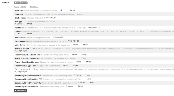
Shown below is an example job setup screen. Each of the inputs are either fixed drop-down lists or are tested against a regex validation string. This ensures that the generated configurations are always using consistent data. If the site name needs to be in ‘Title Case’ then it won’t let you proceed until it is entered correctly, perfect for anal people like me.

RundeckOptions

When defining a drop-down list of options, you have to point Rundeck at a web address with a JavaScript Object Notation (JSON) feed containing the data. This is where the aforementioned Network Interrogation Tool (NIT) comes in. NIT is a web service written in Python/Flask that sits in the middle between SolarWinds and Rundeck to provide Rundeck with the various lists of options that the user must select for each job.

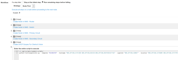
Once we have all of the required variables, we can call scripts with command line options to perform the various tasks for us.

RundeckWorkflow

As of today we perform the following actions, but they can be expanded easily.

  • Create the DHCP scopes.
  • Create the nodes in NMS for monitoring.
  • Generate the router and switch configurations.
  • Add any tasks that can’t be automated to Asana.

RundeckExecution

I will go in to some of the detail of the Python scripts in a later part of this series.

Rundeck does much more than outlined here, but for our purposes it is enough to define jobs that capture sanitised variables from the user and then call scripts that perform a series of actions.

That’s probably a good place to stop on the front-end side of things.